Unified Modeling Language (UML)
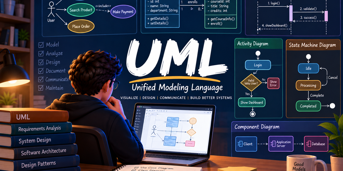
Before writing a single line of production code, clear systems are designed visually. Unified Modeling Language (UML) is the standardized visual language software engineers use to specify, visualize, construct, and document the artifacts of a software system.
Without clear visual blueprints, complex Low-Level Design (LLD) decisions get lost in verbal discussions, leading to architectural mismatch and costly refactoring down the line.
The Two Main Pillars of UML
UML diagrams fall into two primary categories based on what perspective of the system they represent:
1+-----------------------------------------------------------------+2| UML DIAGRAMS |3+-----------------------------------------------------------------+4 | |5 v v6+-------------------------------+ +-------------------------------+7| Structural (Static) | | Behavioral (Dynamic) |8| | | |9| Shows what components exist | | Shows how components interact |10| in the code layout. | | and change state over time. |11+-------------------------------+ +-------------------------------+12 | |13 v v14+-------------------------------+ +-------------------------------+15| Focus: Class Diagram | | Focus: Sequence Diagram |16+-------------------------------+ +-------------------------------+
1. Structural (Static) UML Diagrams
Structural diagrams model the static organization of a system. They outline components, class blueprints, attributes, and relationships without dealing with execution time or dynamic logic.
- Diagram Count: There are 7 structural diagrams in standard UML (Class, Component, Deployment, Object, Package, Composite Structure, and Profile Diagrams).
- Core Focus in LLD: Out of these 7, we focus heavily on the Class Diagram. The remaining 6 diagrams deal with specific deployment setups, high-level packaging, or hardware layouts, which are highly case-specific and rarely used during low-level application design.
2. Behavioral (Dynamic) UML Diagrams
Behavioral diagrams model how a system behaves at runtime. They illustrate dynamic execution, message flows, state transitions, and object interactions over time.
- Diagram Count: There are 7 behavioral diagrams in standard UML (Sequence, Use Case, Activity, State Machine, Communication, Interaction Overview, and Timing Diagrams).
- Core Focus in LLD: Out of these 7, we focus primarily on the Sequence Diagram. The other 6 diagrams cater to broad business processes or hardware timing specifications, whereas the Sequence Diagram directly models method invocations and runtime message passing between objects.
Class Diagram Essentials
A Class Diagram is a structural diagram that represents the static blueprint of your application by showing classes, their attributes, methods, and access boundaries.<br> We represent class structures and associations or connections in a class diagram.
Class structures:
1. Anatomy of a Class Block
In UML, a class is rendered as a rectangle divided into three horizontal compartments:
1+-----------------------------------+2| ClassName | <-- 1. Class Name3+-----------------------------------+4| - attributeName : DataType | <-- 2. Attributes (Variables)5+-----------------------------------+6| + methodName(param : Type) : Type | <-- 3. Operations (Methods)7+-----------------------------------+
- Top Compartment: The name of the class or interface.
- Middle Compartment: Fields and member variables with their data types.
- Bottom Compartment: Methods, parameters, and return types.
2. Access Modifiers
Visibility of attributes and methods is defined using standard UML symbols:
| Symbol | Visibility | Java Equivalent |
|---|---|---|
+ | Public | Accessible from any class |
- | Private | Accessible only within the defining class |
# | Protected | Accessible within the package and subclasses |
~ | Package / Default | Accessible only within the same package |
3. Abstract Classes and Interfaces
UML uses specific notation to distinguish concrete classes from abstract types and contracts:
Abstract Class <br>
An abstract class cannot be instantiated directly and is denoted by rendering the class name in italics, using the {abstract} property tag or using the «abstract» stereotype at the top of the block.
1«abstract»2+-----------------------------------------------------+3| PaymentGateway |4+-----------------------------------------------------+5| # merchantKey : String |6+-----------------------------------+7| + processPayment(amt: double) : void {abstract} | <-- Abstract Method8+-----------------------------------------------------+
Interface <br>
An interface defines a pure contract and is denoted using the <<interface>> stereotype at the top of the block.
1<<interface>>2+-----------------------------------+3| Notification |4+-----------------------------------+5| + sendNotification(msg: String) |6+-----------------------------------+
Associations & Relationships
In UML, an Association defines how two or more classes interact or connect with each other. Associations are broadly categorized into two types:
- Class Association — Defined at compile-time via structural relationships like inheritance.
- Object Association — Defined at runtime via instance references (Simple Association, Aggregation, Composition).
Class Association (Inheritance)
A Class Association represents an "IS-A" relationship. It signifies that a child class inherits the fields and behaviors of a parent class or implements the contract defined by an interface.
1. Generalization (Class Inheritance) Used when a subclass extends a superclass.
- UML Symbol: A solid line with a hollow/filled triangle (
───▷) arrowhead pointing from the child class to the parent class.
2. Realization (Interface Implementation) Used when a class implements an interface.
- UML Symbol: A dashed line with a hollow/filled triangle (
── ── ▷) arrowhead pointing from the implementing class to the interface.
1«interface»2 +-----------------------+3 | PaymentGateway |4 +-----------------------+5 ^6 | (Realization: Dashed Line)7 |8 +-----------------------+9 | BaseCardProcessor |10 +-----------------------+11 ^12 | (Generalization: Solid Line)13 |14 +-----------------------+15 | CreditCardProcessor |16 +-----------------------+
The solid line in diagram may also look like a dashed line, but for showing inheritance from class we use solid line with filled or hollow arrow (
───▷).
1// Interface2public interface PaymentGateway {3 void processPayment(double amount);4}56// Parent Abstract Class (Realization)7public abstract class BaseCardProcessor implements PaymentGateway {8 protected String merchantId;910 public BaseCardProcessor(String merchantId) {11 this.merchantId = merchantId;12 }13}1415// Child Class (Generalization)16public class CreditCardProcessor extends BaseCardProcessor {17 public CreditCardProcessor(String merchantId) {18 super(merchantId);19 }2021 @Override22 public void processPayment(double amount) {23 System.out.println("Processing credit card payment of $" + amount + " via merchant: " + merchantId);24 }25}
Object Association
An Object Association represents a "HAS-A" relationship between instances at runtime. Unlike class associations (inheritance), object associations define how objects hold references to other objects.
Object associations are categorized into three levels based on the strength of ownership and lifecycle dependency:
1Simple Association ---> Aggregation ---> Composition2(Weakest) (Stronger) (Strongest)
Note on Implementation: In actual code, all three associations look virtually identical—a class holding a field reference to another class. The distinction between simple association, aggregation, and composition exists purely at the conceptual/design level to define ownership and lifecycle dependencies.
1. Simple Association (Weakest) <br>
- Concept: Represents a loose, peer-to-peer connection between two independent objects. Neither object owns the other, and both can exist completely independently.
- UML Representation: A plain solid line (optionally with an open arrow
───>indicating navigation direction).
2. Aggregation (Stronger) <br>
- Concept: Represents a "whole-part" relationship where a parent object contains a child object, but the child object can exist independently if the parent is destroyed.
- UML Representation: A hollow diamond
◇───attached to the owner (parent) object.
3. Composition (Strongest) <br>
- Concept: Represents a strict "whole-part" relationship where the child object cannot exist independently without the parent object. If the parent is destroyed, the child object is destroyed with it.
- UML Representation: A filled diamond
◆───attached to the owner (parent) object.
Comprehensive Example: All-in-One Class Diagram
To understand all these relationships in a single context, consider a Person driving a Car:
- Person and Car $\rightarrow$ Simple Association (A Person uses a Car (Person has-a Car), but both exist independently)
- Manual Car and Electric Car extend Car $\rightarrow$ Generalization / Inheritance (IS-A relationship)
- Car and Engine / Battery $\rightarrow$ Aggregation (An Engine or Battery can exist outside a specific Car)
- Car and Tyre / Windscreen $\rightarrow$ Composition (Tyres and Windscreens are integral parts tied strictly to the Car instance)
1+--------------+ +------------------+23 | Person |───────────────────>| Car |4 +--------------+ Simple Association +------------------+5 ◆ ▲ ◇6 / | \7 Composition / | \ Aggregation8 / | \9 / | \10 +--------------+ | +---------------+11 | Tyre | | | Engine |12 +--------------+ | +---------------+13 |14 │15 │ Generalization (IS-A)16 │17 +--------------+18 | ElectricCar |19 +--------------+
1```java2// 1. Independent components (Engine for Aggregation)3public class Engine {4 private String engineNumber;56 public Engine(String engineNumber) {7 this.engineNumber = engineNumber;8 }9}1011// 2. Tightly bound components (Tyre for Composition)12public class Tyre {13 private String brand;1415 public Tyre(String brand) {16 this.brand = brand;17 }18}1920// 3. Parent Class managing Aggregation, Composition, and Inheritance21public abstract class Car {22 // Composition: Tyres are created inside the Car constructor (Tight Lifecycle)23 private final List<Tyre> tyres;2425 // Aggregation: Engine is passed in from outside (Independent Lifecycle)26 private Engine engine;2728 public Car(Engine engine) {29 this.engine = engine; // Aggregation30 this.tyres = List.of( // Composition31 new Tyre("Michelin"),32 new Tyre("Michelin"),33 new Tyre("Michelin"),34 new Tyre("Michelin")35 );36 }3738 public void setEngine(Engine engine) {39 this.engine = engine;40 }41}4243// Inheritance (IS-A)44public class ElectricCar extends Car {45 public ElectricCar(Engine electricMotor) {46 super(electricMotor);47 }48}4950// 4. Driver class representing Simple Association51public class Person {52 private String name;5354 public Person(String name) {55 this.name = name;56 }5758 // Simple Association: Car is passed as a method parameter (Weak Connection)59 public void drive(Car car) {60 System.out.println(name + " is driving the car.");61 }62}
Sequence Diagrams: Modeling Dynamic Interactions
While Class Diagrams capture the static skeleton of your application, Sequence Diagrams illustrate the dynamic runtime behavior. They show how objects interact, exchange messages, and execute business logic in a strict time-ordered sequence.
Key Components of a Sequence Diagram
Every sequence diagram uses four primary visual elements:
1[ Object / Class ] <-- 1. Participant Block2 |3 | <-- 2. Lifeline4 |5 +---+6 | | <-- 3. Activation Bar (Focus of Control)7 | | === Message ==> <-- 4. Message Line8 +---+9 |
- Participant / Class: Represents the object or system entity participating in the interaction (placed horizontally at the top).
- Lifeline: A vertical dashed line extending downward from each participant, representing the existence of the object over time.
- Activation Bar (Execution Specification): A thin vertical rectangle overlaid on a lifeline showing when an object is actively executing a method or processing an operation.
- Message Lines: Horizontal arrows drawn between lifelines showing data exchanges, method calls, or responses.
Message Types & Notation
Messages define how objects communicate. The shape of the arrowhead indicates the exact nature of the interaction:
| Message Type | Symbol / Line Style | Description | Code Mapping |
|---|---|---|---|
| Synchronous Message | ──────► (Solid line, filled arrow) | Sender blocks and waits for a response before continuing execution. | Regular method call: a.doSomething() |
| Synchronous Reply | - - - -► (Dashed line, open arrow) | Return value or control flowing back to the caller. | Method return statement: return result; |
| Asynchronous Message | ──────> (Solid line, open arrow) | Sender fires the message and immediately continues without waiting. | Thread/Executor, Event, Queue message |
| Create Message | - - - -► «create» | Instantiates a new participant object during execution. | Object instantiation: new Order() |
| Destroy Message | ──► ✖ (Target ended with 'X') | Explicitly terminates an object lifeline. | Object destruction / explicit cleanup |
| Found Message | ●─────► (Filled circle to lifeline) | Message originates from an unknown or external source outside the system scope. | Inbound webhook, system signal |
| Lost Message | ──────► ● (Lifeline to filled circle) | Message sent to a target that is outside the system scope or unhandled. | Log output, unhandled notification |
Step-by-Step Guide: How to Draw a Sequence Diagram
To construct a clear and readable sequence diagram for Low-Level Design:
- Identify the Use Case Scope: Define the single business flow or endpoint you want to model (e.g., User Places an Order).
- Identify Participating Objects: List the specific classes/services involved in this workflow from left to right in order of initial interaction.
- Establish Lifelines: Draw vertical dashed lines extending downward from each participant block.
- Draw Sequential Messages (Top to Bottom): Lay out method calls chronologically from top to bottom.
- Add Activation Bars & Replies: Overlay activation bars on lifelines to mark active processing periods and draw dashed return lines where necessary.
Sequence Diagram Example: Order Checkout Flow
1@startuml2autonumber34actor User5participant ClientApp6participant OrderService7database PaymentGateway89User -> ClientApp : placeOrder()10activate ClientApp1112ClientApp -> OrderService : processOrder()13activate OrderService1415OrderService -> PaymentGateway : charge(amount)16activate PaymentGateway17PaymentGateway --> OrderService : txSuccess18deactivate PaymentGateway1920OrderService -> OrderService : sendAsyncEmail()21note right: Async Message2223OrderService --> ClientApp : orderSuccess24deactivate OrderService2526ClientApp --> User : Display Conf27deactivate ClientApp2829@enduml
1User ClientApp OrderService PaymentGateway23 | | | |4 |--placeOrder()-->| | |5 | |--processOrder()->| |6 | | |--charge(amount)->|7 | | |<---txSuccess-----|8 | | | |9 | | |--sendAsyncEmail()| (Self-loop Async)10 | | |<--orderSuccess---|11 | |<--Display Conf-| |12 | | | |
In real-world application design, a single system handles dozens of interactions. Because of this, a system does not have just one sequence diagram—you create one Sequence Diagram per Use Case (e.g., Successful Payment, Failed Checkout, User Cancellation).
To model complex business logic like conditional execution and loops within a single Sequence Diagram, UML provides Combined Fragments<br> Combined Fragments:
alt(if-else),opt(if), andloop(for/while)